I am known in the cryptoworld as Emdje on the Bitcointalk forum. Some time ago I bought myself an A2 mini. After a while I wanted to overclock my miner and add more options to it. However the software was closed source so there was little I could change. By asking I was approached by someone who had the source. Since then I have been adding frequency options to the software, as well as extranonce support. The software runs on all A2 boards with 6 chips on it (so not the new ones with 8 or 10). If you want to boost your miners performance or lower it to save some power? Check it out at: https://bitcointalk.org/index.php?topic=672969.0
DISCLAMER: Before we continue I would like to stress that this procedure is completely done at your own risk. There is a chance that you could damage something and in the process break your miner.
Having said that, here is all you need to voltagemod your A2 board:
– Tweezers
– For each board; 4 x 12.7k ‘normal’ resistor (high precision)
– Soldering flux
– Small solder
– Thin tipped soldering iron
– Thinner, or 90% + isopropyl alcohol
– Old toothbrush
– Cooling paste
– Optional: Magnifying glass
– Optional: Anti-static mat
Step one: Take out the board you want to mod out of the box.
Step two: Screw the heatsinks off of the board. If you don’t do this you will have difficulty soldering because all the heat from the soldering iron is conducted right away from the components.
Step three: Clean the board, heatsinks and silicone mats from the old cooling paste. I used thinner for that, works fine. You should of course do this in a well ventilated area.
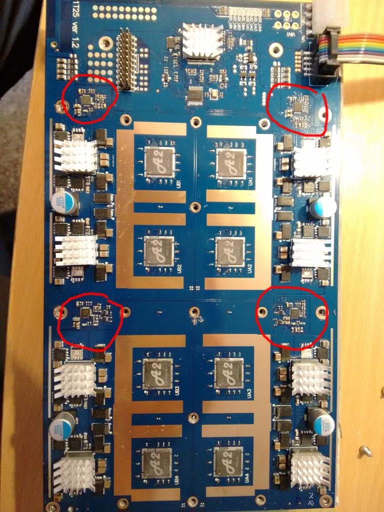
Step four: Locate the voltage regulators and the resistors you need to replace. In the picture the voltage regulator circuit are circled
with red.
The configuration of the voltage regulator circuit
is different in all four. The resistor that we are
looking
for is the resistor marked ‘05C’ (the one where the
red arrow points to in the picture). This resistor
is
always next to a capacitor and a blank space.
This resistor is always next to a capacitor and a blank space.

Step five: Put some flux on the resistors, heat up both sides and use the soldering iron to push it off. The resistor will most likely stick to the soldering iron so shake it off onto a peace of toilet paper, or at least on something that makes sure it does not bounce away. Resolder the two contact points with some new solder, and put some flux on it, so that there is a nice fresh bump ready for its new component.
Step six: Take a 12.7k resistor, fold it so that the two legs are about 1.5 mm apart. Cut them into the right length and rough up the legs so the solder adheres better. First, solder the legs of the resistor.
Then, take the tweezers and hold the resistor on the two contact points. Use the thin tipped soldering iron to one by one secure the legs to the board. Check to see if the solder does not flow to any other components or contacts. If so, put some flux on it and use a clean soldering tip to resolder it.
Step seven: After you have repeated this four times on each board you take an old toothbrush (or a new one if you like the taste :p ) and some thinner (or isopropyl alcohol) to clean off the unneeded flux from the voltage regulator circuit.
Step eight: Use your multimeter to measure the resistance of your new resistors. When you measure them you will register a much lower value than the 12.7k, that is because you measure it in a circuit and not ‘stand alone’. None the less, they should all read the same value. If they don’t check you soldering for any visible short circuit. No visible short circuit, take of the resistor, measure it separately, and if right value put it back on the board and measure again.
Step nine: Put some new cooling paste on the chips (NOT TO MUCH) and screw the heatsinks back on. I put a very thin layer of cooling paste between the silicone pad and the heatsinks as well.
Step ten: Screw the board back into its housing and check your work. (MAKE SURE YOU HAVE GOOD COOLING. I LOST A CHIP, AND THUS A BOARD, BECAUSE OF A COOLING F*CKUP).
Other resistor values and the (theoretical) voltage output:
03c – 10.5k : 0.828 V
05c – 11k : 0.840 V
09c – 12.1k : 0.880 V
10c – 12.4k : 0.902 V
11c – 12.7k : 0.924 V
Max 12.79k : 0.930 V
I hope you like my guide, and if you like my work and effort I have put into this you can donate some sandwiches (I don’t drink beer 😉 ) to 1FiHCFcP4ovbV89nGhYEMWXSZsWnGUASSe
For any questions you can reach me on Bitcointalk.
Thanks to kingscrown for publishing this guide!
Helped or Loved it? Drop a Coin!
* BTC of author 19wQNfe4FKqeYFTAmNTzNLMUDtQTv4SyQ4
* BTC 197arptA1JLA3NvBz5ci2Ddm8ZhuvdEj38
* LTC Lcy9nsfJeSA5Rvu61xiXPKUH1VyV9hwupL
* DOGE DJcER4WrKUVyuECZCZ2vBWfK2E9d212jcQ
